Here is the previous post on this project for those that are following along:
http://langster1980.blogspot.co.uk/2017/05/graphing-data-from-venturi-tube.html
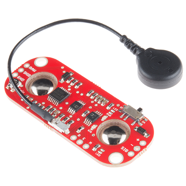
I received in the post a Myoware EMG (Electromyography) sensor kit available from Sparkfun and other vendors. The webpage for the product is shown below:
https://www.sparkfun.com/products/13723
The idea with this circuit is to sense muscle movement when a person breathes in and out and from that correlate lung function. How much air a person can breathe in and out is partly to do with muscle (diaphragm) and chest movement - I'm not a medical doctor so I'm a little out of my depth here...however it was part of the functionality requested for the medical device so I'm investigating solutions and this circuit is one solution. Lets see how well it works and get some data and compare it to what would be expected. As a healthy male of some 30+ years (in my prime!) it should show that I'm a paragon of excellence...in reality I suspect it will show that my heart and muscle function are average but more importantly present!
Here are the instructions for use:
https://github.com/AdvancerTechnologies/MyoWare_MuscleSensor/blob/master/Documents/AT-04-001.pdf
The board itself is very simple to setup and use and the instructions are clear and concise.
This is the setup I'm going with...I'm certain there shouldn't be any issues but I don't have the buffer circuit so...it's time to man up!
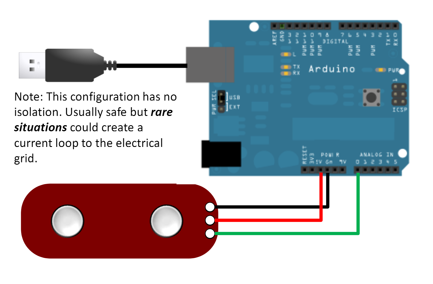
(I had both the raw and sig output connected to my arduino analogue inputs A0 and A1)
//test code for Myoware EMG PCB
// variables for input pin from MyoWare PCB
int analogInputSig = A0;
int analogInputRaw =A1;
// variables to store the values
int valueSig = 0;
int valueRaw = 0;
void setup() {
pinMode(analogInputSig, INPUT);
pinMode(analogInputRaw, INPUT);
// begin sending over serial port
Serial.begin(9600);
}
void loop() {
// read the values from the sensor:
valueSig = analogRead(analogInputSig);
valueRaw = analogRead(analogInputRaw);
//print the reading received
Serial.print(valueSig);
Serial.print(",");
Serial.print(valueRaw);
Serial.println();
// wait for a bit to not overload the port
delay(10);
}
Here is the serial output graphed for your viewing pleasure:
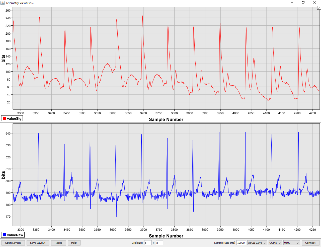
Here is my wife's heart rate...apparently I don't have quite the effect on her I used to!

Here is what happens when the sensors are placed on the abdomen:
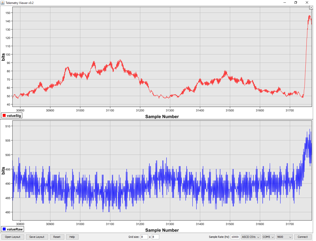
So...I'm alive and so is the wife! The Myoware picks up a good strong electrical signal when sensors are placed close to the heart...but when placed on the abdomen did not really pick up anything I could see correlating to breathing or diaphragm movement. Either I had my sensors incorrectly placed or the circuit is not sensitive enough for this purpose. Adjusting the gain potentiometer on the Myoware PCB did change the gain response but didn't provide the response I was looking for - It was hoped that it would be possible to correlate diaphragm muscle movement with regular breathing.
I did notice that if I activated (flexed) my abdmoninal muscles electrical signals were definitely present and well detected...maybe I don't use my diaphragm much when I breathe in and out? I will have to investigate further.
I could not find a schematic diagram for the Myoware circuit although the shields are marked as being open source. Update - See comments below from Brian Kaminsky of Advancer Technologies.
Here is the schematic for the previous version of the device:
https://cdn.sparkfun.com/datasheets/Sensors/Biometric/Muscle%20Sensor%20Platinum%20v3.3.pdf
The main integrated circuit is an AD8648 which is a quad operational amplifier. I suspect the two smaller devices are programmable gain devices for each of the sensor inputs and the rest of the components are associated gain and filtering requirements.
Here is the datasheet for the AD8648
http://www.analog.com/media/en/technical-documentation/data-sheets/AD8646_8647_8648.pdf
Here is the datasheet for the devices marked AD A 1V (An AD 628 I think....)
http://www.analog.com/media/en/technical-documentation/data-sheets/AD628.pdf
The company (Advancer Technologies) that developed the Myoware PCBs also wrote this instructable which shows how a similar circuit could be developed:
http://www.instructables.com/id/Muscle-EMG-Sensor-for-a-Microcontroller/
I have seen similar circuits in the past and believe this is certainly one route to achieving the measurement of electrical signals either from the heart (ECG - ElectroCardioGrapy) or muscle movement (EMG - ElectroMyoGraphy).
I would certainly say that this circuit has been very well designed and implemented and would be very useful if one wanted to use muscle flexing signals to control an external device or detect when someone has used a muscle...so say for instance you wished to mirror your arm movement with a robotic arm then this is definitely the circuit for the job!
That is all for now - take care always, Langster!
No comments :
Post a Comment