CAN Bus Wikipedia Enry
Here are a few other pages which might be of interest:
http://canbuskit.com/what.php
http://www.canbus.us/
http://www.kvaser.com/can-protocol-tutorial/
The topic is quite dry to say the least. I'm not going to go into the detail about CAN Bus but rather very briefly explain what it does and how it works and then provide an example. In a modern vehicle the instrument panel communicates with a central microcontroller inside the engine known as the Engine Control Unit or ECU. The ECU is also communicating with sensors inside the engine so that the vehicle speed, gear, engine temperature, oil temperature, coolant temperature etc are all known. This information from the sensors is used to control the engine and is displayed via the instrument panel. The way this data is communicated uses CAN Bus.
CAN Bus is a two wire protocol - messages are sent as frames on two conductors known as CAN H and CAN L (CAN High and CAN Low). Although more often a four wire system is used where power and ground are also present.
The speed of communications governs the length of cable between the master and nodes. For the top speed of 1Mbit/Sec this is 40 metres in length or less. If less speed is required the length of the cable can be longer.
| Bus Speed | Bus Length (L) | Cable Stub Length (l) | Node Distance (d) |
| 1 Mbit/Sec | 40 meters (131 feet) | 0.3 meters (1 foot) | 40 meters (131.2 feet) |
| 500 kbits/Sec | 100 meters (328 feet) | 0.3 meters (1 foot) | 100 meters (328 feet) |
| 100 kbits/Sec | 500 meters (1640 feet) | 0.3 meters (1 foot) | 500 meters (1640 feet) |
| 50 kbits/Sec | 1000 meters (3280 feet) | 0.3 meters (1 foot) | 1000 meters (3280 feet) |
Information from the 1st node to the 2nd node is sent in frames (packets of information). There are four different types of frame - Data, Remote, Error and Overload.
A Frame itself is made up of bits (ones and zeros in a pattern).
If you were to look at a frame using a logic analyser you might see something like this:
The start of the frame the logic goes from High to Low to High (transition). The identifier is sent next (a specific code made up of highs and lows which tell the receiver what type of frame it is...this is followed by another high to low to high transition known as the RTR - ready to receive. That whole section is known as the arbitration field - it tells the receiver what kind of frame has been received and that the receiver needs to respond. The next section is called the control field which is followed by the data field. After that a cyclic redundancy check (CRC) is performed to ensure that the data was received correctly. Lastly an acknowledge transition to mark the end of the frame is seen.
Rather than concentrate on the theory of operation lets discuss how to implement a CAN Bus system using the mbed microcontroller - you will need two mbeds, a length of 2 core wire, 2x 120R resistors and hookup wires. You will also need two CAN Bus tranceivers - there are many different versions of these devices available. I'm using the MCP2551 from Microchip. A CAN Bus tranceiver is an eight pin integrated circuit designed to transmit and receive CAN Bus messages. The link to the datasheet for the MCP2551 is below:
MCP2551 datasheet
Lets implement a simple circuit which flashes an LED when a valid message sent from one node and when this message is received by another node a different LED flashes.

Here is how are how things looks when the above circuit is implemented:
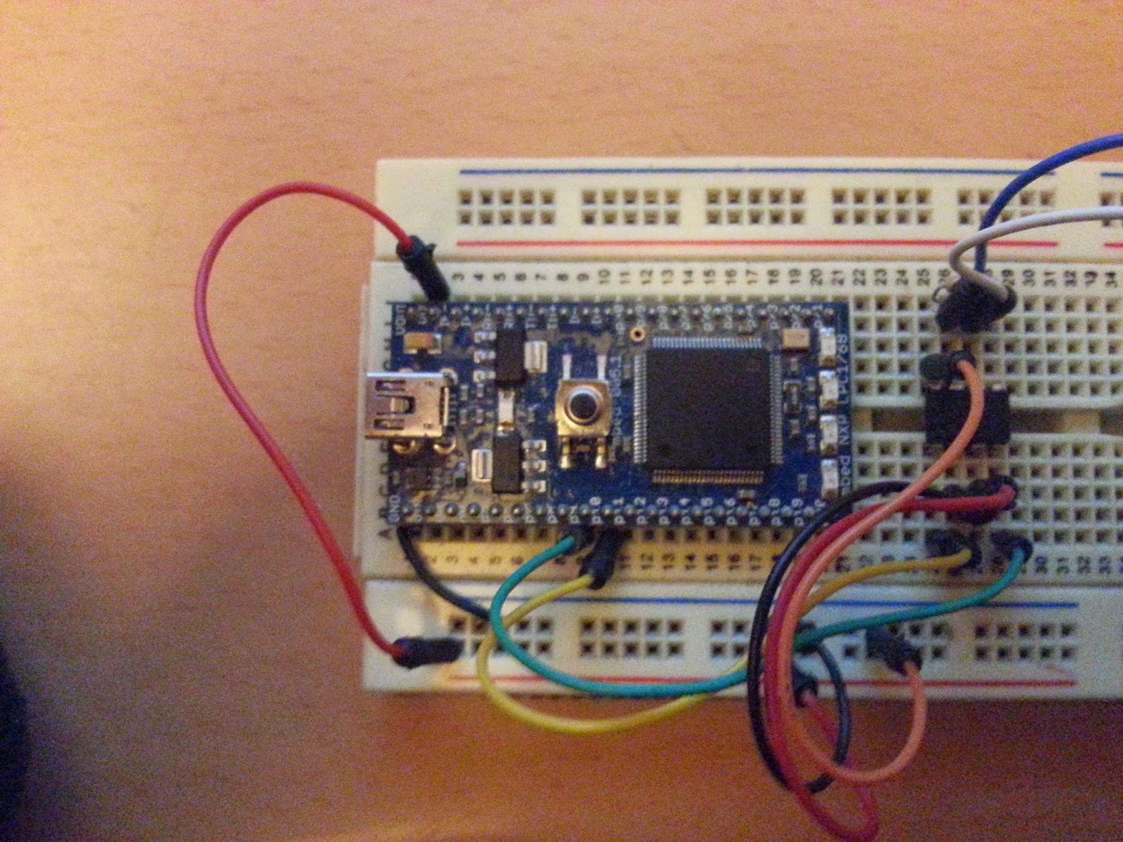 |
| 1st mbed - The CANbus Transmitter |
 |
| 2nd mbed - The CANbus Receiver |
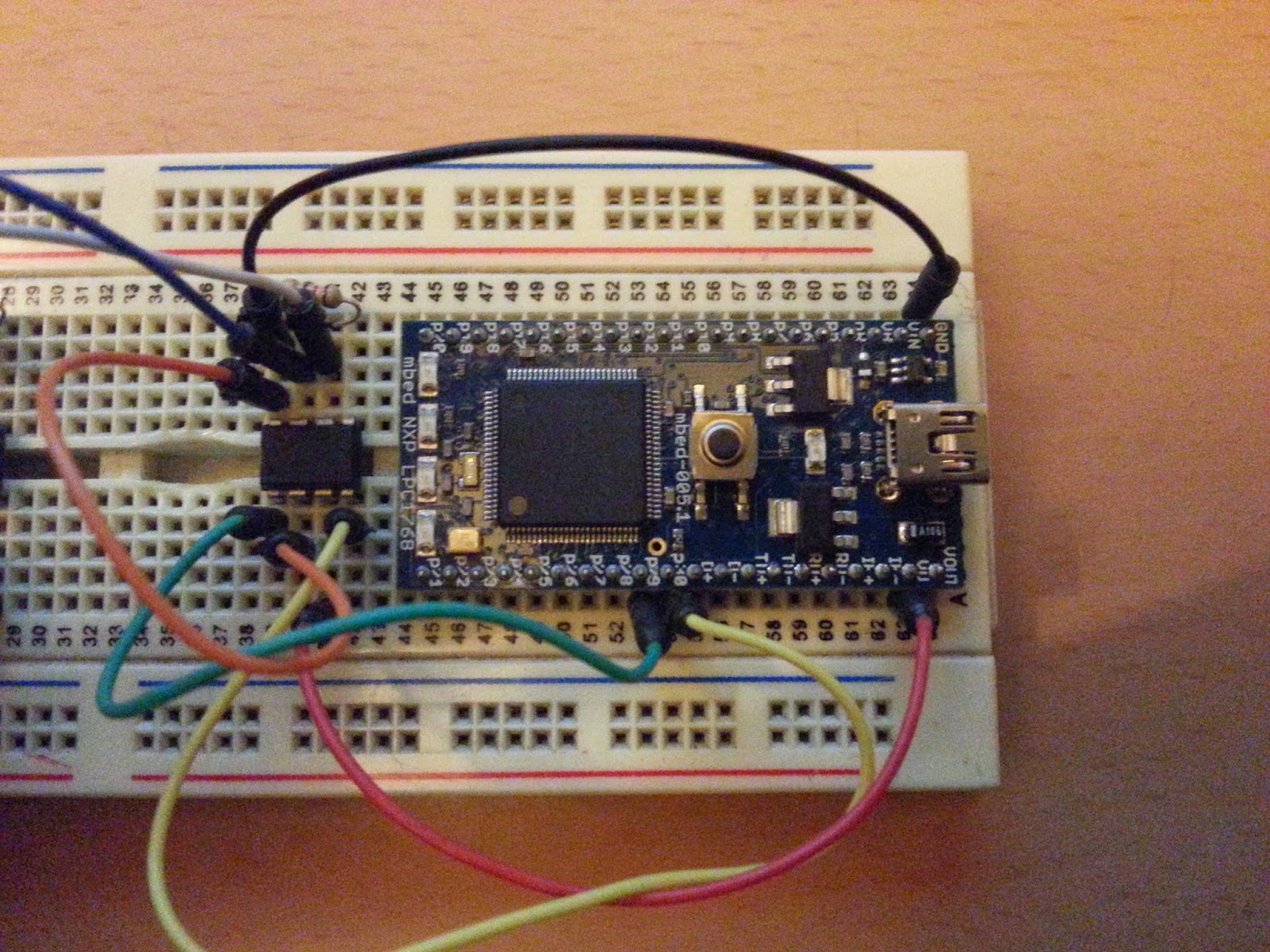
I'm going to use a length of multicore alarm cable to connect both microcontrollers together making up the 'CAN Bus'. However if you wanted you could just use two short wires and have both mbeds on the same breadboard:
 |
| Both mbeds - ready to go! |
/*
Transmitter code
CANBus Tutorial based on lots of example code
*/
#include "mbed.h"
Serial pc(USBTX, USBRX); // tx, rx for Tera Term output
DigitalOut led1(LED1); // LED1 displays messsage sent Status
CAN can1(p9, p10); // CAN interface
char counter = 0; // Counter Variable to store number of sent messages
int main() {
printf("sending a message via CANbus... ");
while (1) {
// send value to CAN bus and monitor return value to check if CAN
// message was sent successfully. If so display, increment and toggle
if (can1.write(CANMessage(1, &counter, 1))) {
pc.printf("CANBus Message sent: %d\n", counter); // display message
counter++; // increment message counter value
led1 = !led1; // toggle LED1 to show message sent
}else{
can1.reset(); // Reset CANbus if there is a problem
}
wait(1); // wait a second
}
}
/*
Receiver code
CANBus Tutorial based on lots of example code
*/
#include "mbed.h"
Serial pc(USBTX, USBRX); // tx, rx for Tera Term output
DigitalOut led2(LED2); // status LED
CAN can1(p30, p29); // CAN interface
int main() {
CANMessage msg; // create empty CAN message
printf("received a CANbus message...\n"); // Write to serial terminal
while(1) {
if(can1.read(msg)) { // if message is available, read into msg
printf("Message received: %d\n", msg.data[0]); // display message data
led2 = !led2; // toggle receive status LED
}
}
}
Here is a picture of the terminal windows showing the serial messages:

Here is a video showing the circuit working....apologies for the wiring issues!
I had real trouble getting this to work...check your wiring very carefully. The mbed whilst good in principle is very hard to wire up correctly. I am seriously considering obtaining a decent mbed motherboard to make these tutorials easier for me. I tried using the Arch-pro mbed from Seeed studios to act as the second mbed but just could not get it to play. I ended up borrowing another mbed from a friend in order to get things working...anyway that's it. Take care - Langster!
Very cool project. I can see that you spent a lot of time on that. I recommend reading these two articles below. They helped me a lot in regards to getting the knowledge about the CAN Bus.
ReplyDeletehttps://www.autopi.io/blog/can-bus-explained/
https://www.autopi.io/blog/discover-hidden-functions-in-your-car-with-can-bus/