Last post was on Field Effect Transistors (FETS). We covered the fact that they are many and varied, are a voltage controlled device and can be used to amplify current or as a kind of semiconductor switch. The key to using FETS is to read the datasheet! The parameters to play close attention to are:
Vds - Voltage between drain and source
Rds - Resistance between drain and source
Vgs Threshold - Voltage at which device will allow current to flow between drain and source
Ids - Amount of current that device will allow to flow between drain and source
Operating Temperature - pretty self explanatory (do not let device get hot - use a heat sink)
Supply Voltage Range - ensure device is rated for supply!
Type - There are several different types of FET, Junction, MOS Insulated Gate, then there are sub types:
N - Type - Enhancement, N - Type Depletion, P Type Enhancment and P-type Depletion.
The most important things to find out are:
Supply Voltage - Don't overdrive device
Vgs Threshold - know when the device turns on or off for control
Ids - How much current can device provide (source)
Everything you need to know should be on the datasheet - as with all semiconductors. It would be nice if datasheets were better written but....good application engineers aren't normally very concise or good at technical writing - here is hoping things improve!
I'm not saying that the other parameters aren't important - they are otherwise they wouldn't be on the datasheet....I believe the three parameters above are the most important to get started. Once the principle works the other parameters can be taken into account. Simulation is the designer's friend! It costs nothing (except for the software and time) and no devices are destroyed :-)
******************
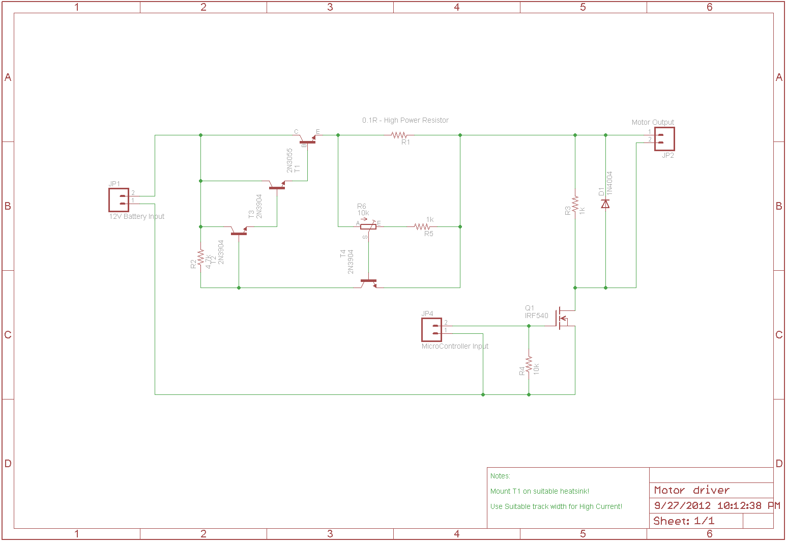
So last time I posted the lads at my local Hackspace were looking for an FET to drive an old electric Scooter. After thinking about things I came up with a simple circuit using an IRF540 N-type Enhancement Mosfet. Now I'm going to add current control with a pass transistor so that we can ensure that no matter what happens the motor can never draw too much current and destroy components. This circuit could also be used to add current control to a variable power supply. Here is the schematic diagram for the current limiting section:

The current limitation circuit is made up of 4 transistors, a variable resistor and two resistors. T4 is a high current 'pass transistor', It's specifically designed to control high currents. We control how it is turned on and off with the three general purpose NPN transistors. The resistor R1 is known as the current sense resistor and is rated to take a large amount of current flow without being damaged.
When power is applied to the circuit at the input the NPN transistor T2 is turned on, this turns on T3 which then turns on T4 the 'pass transistor'. The 4.7k resistor is called a bias transistor which forces the T1 transistor on when a positive voltage is applied to the collector and base.
Because the 'pass transistor' T4 is now on current can flow to the output. The current flow causes a voltage drop to occur across the high power resistor R1. If this voltage drop is greater than 0.7V then the transistor T3 is turned on which turns all of the other transistors off preventing any current flow at the output. The current limit (point at which T3 is turned on) is set by the 10k variable resistor or potentiometer R6. The other resistor R5 is the biasing resistor for T3.
Here is a video simulating the circuit:
So now what we need to do is incorporate the FET driver section that we designed in the last post. Here is the schematic with the motor driver incorporated. You may notice I have connected the potentiometer to the other side of the 'current sense' resistor. This is because we don't need to limit the current completely down to zero. I just want to limit the current from going too high.
Next up is the small PCB that I have designed to test the circuit and maybe use in the scooter. I haven't decided. We might want to incorporate the micro-controller onto this PCB also so that we can contain the electronics all in one place.

Well...that's about it for now. I hope to get this PCB made and tested soon! Until then have fun and be careful - Alex
No comments :
Post a Comment